Design study
79 kWp solar PV and 63 kWh battery system
The mechanical layout, battery control and single line drawings for a 78.88 kWp PV and 63.18 kWh storage design, with an hourly dispatch model.
Drawings and dispatch model
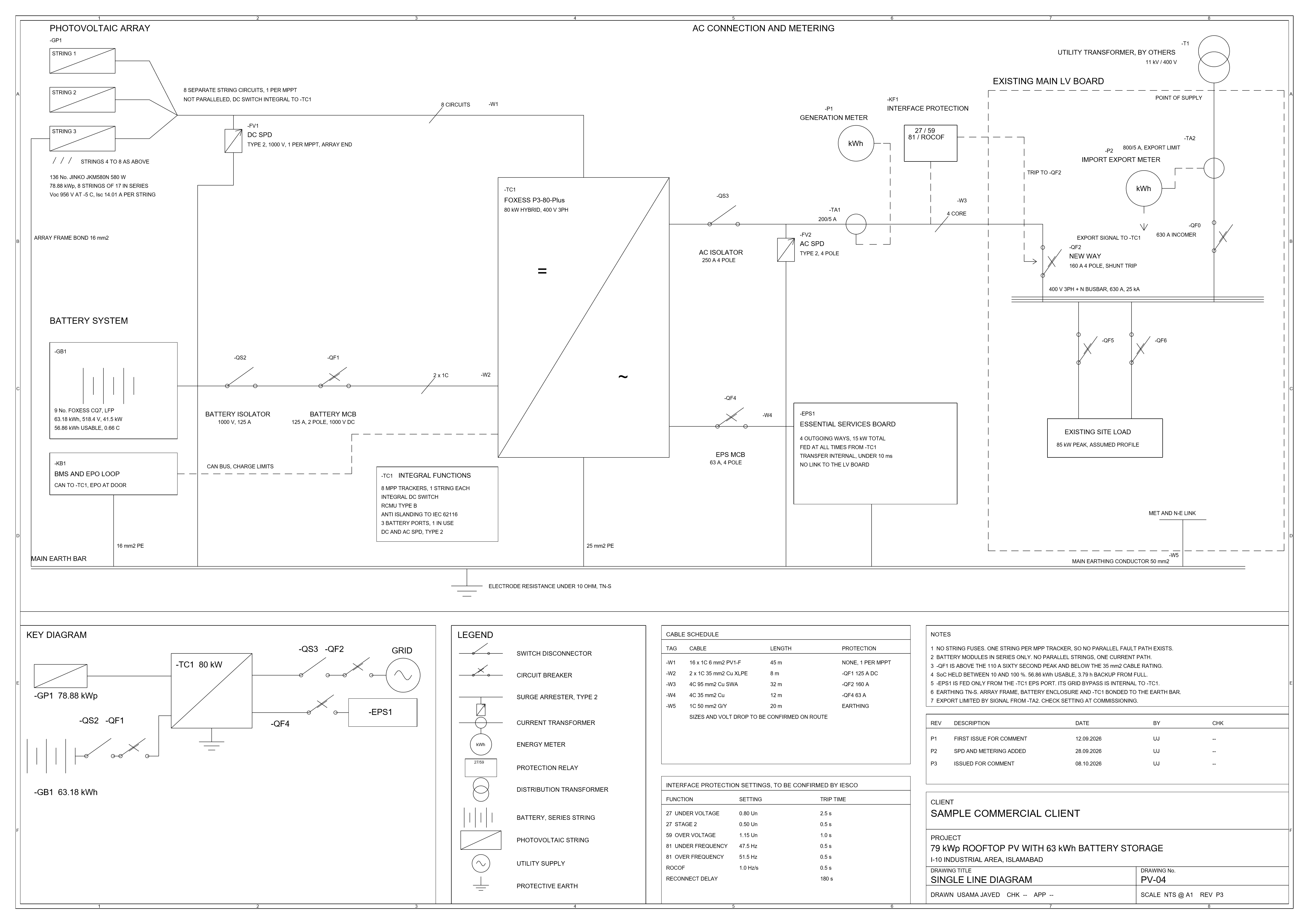
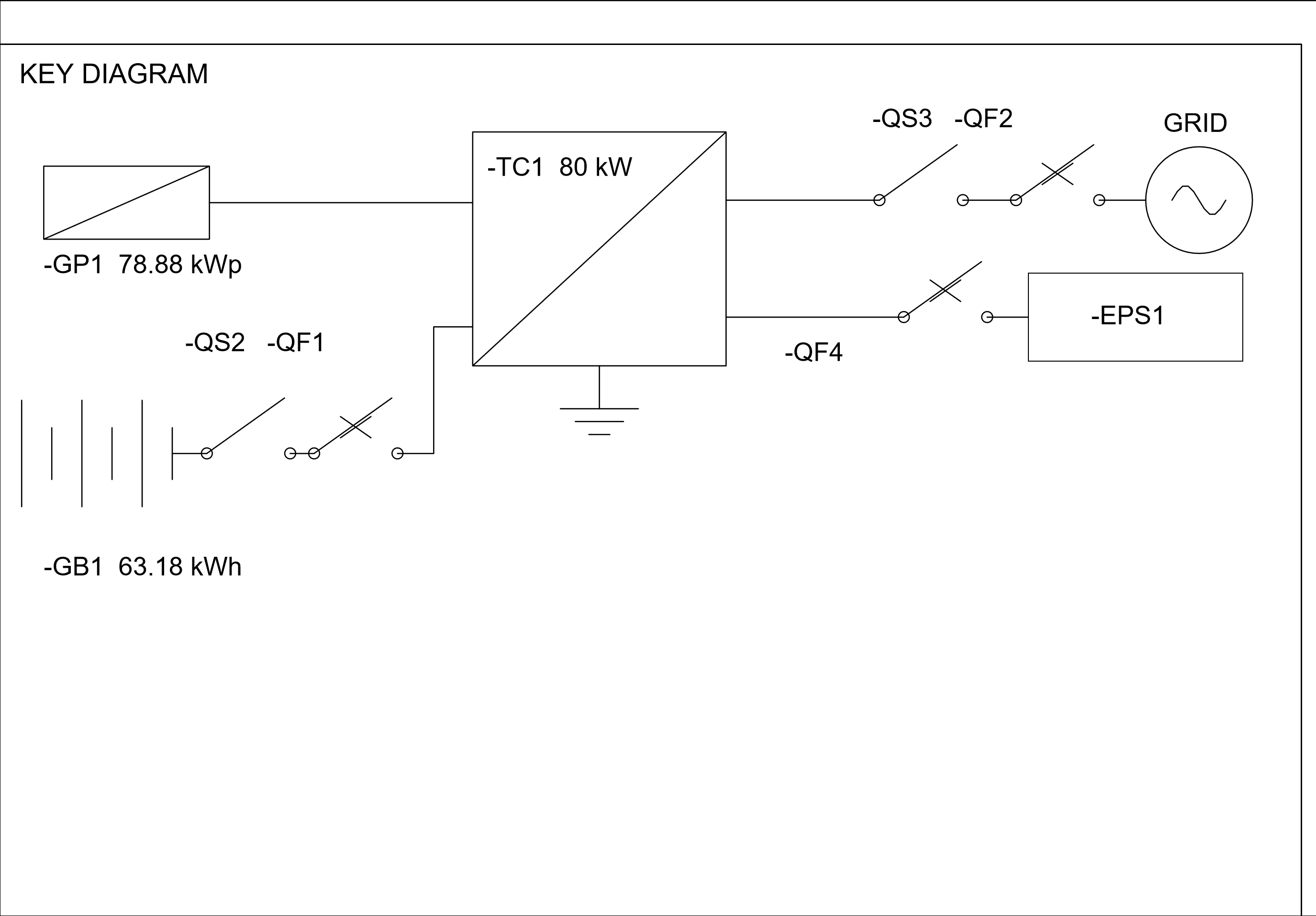
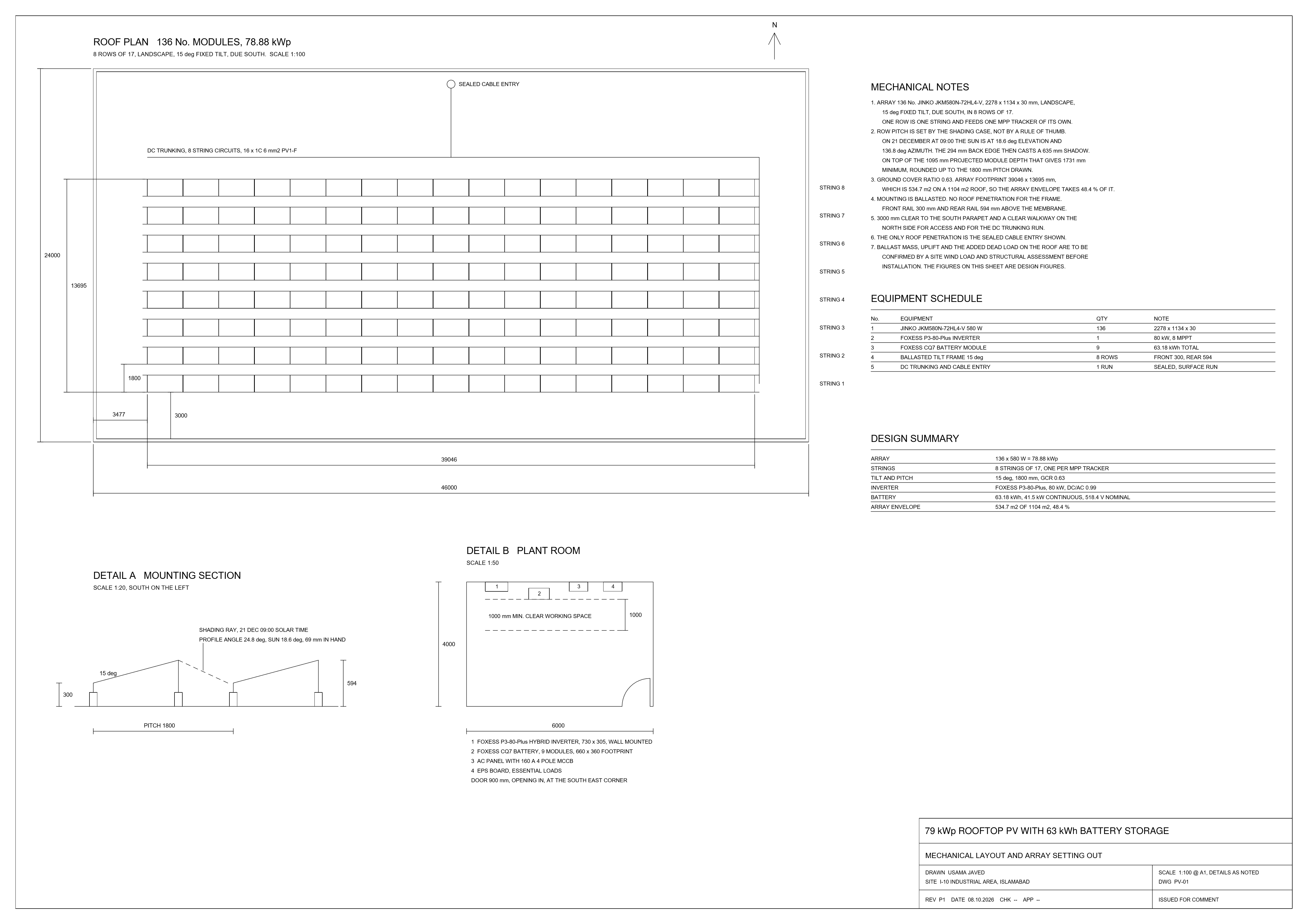
A rooftop PV and battery design study for a commercial unit in Islamabad: 136 Jinko 580 W modules at 78.88 kWp on an 80 kW FoxESS P3-80-Plus hybrid inverter, with nine FoxESS CQ7 modules in series giving 63.18 kWh at 518.4 V.
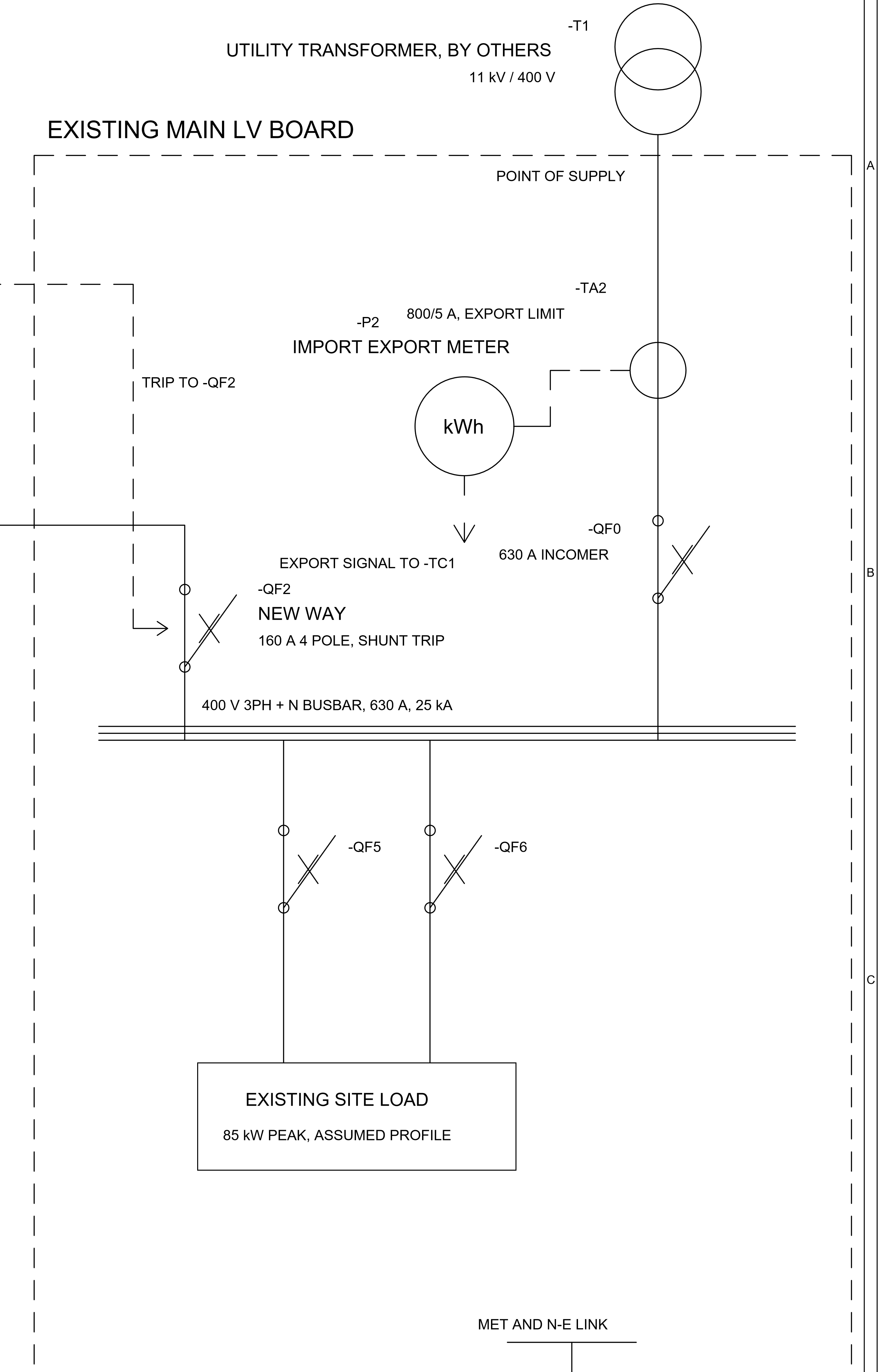
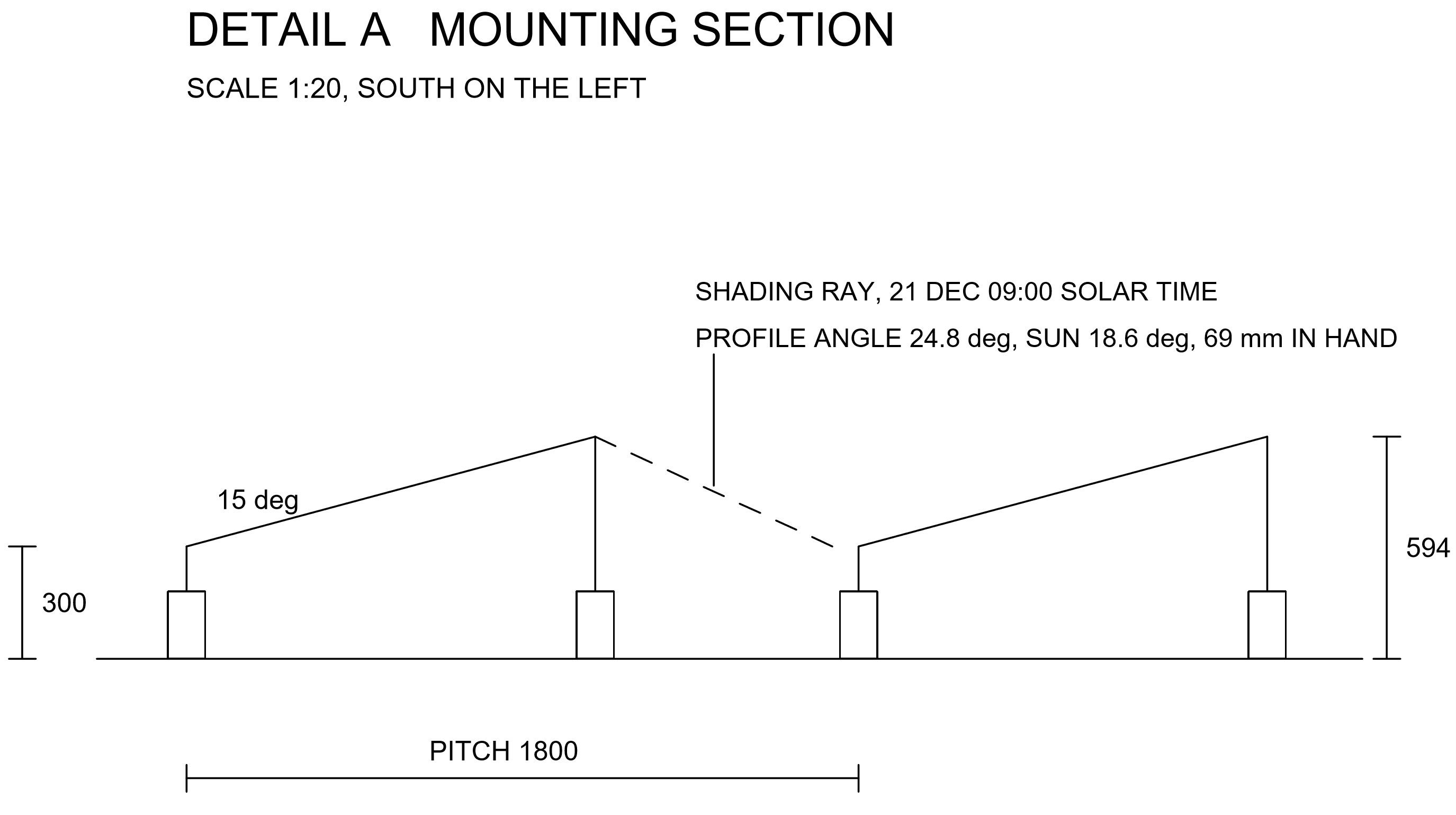
Three A1 sheets drawn in AutoCAD 2027: the single line diagram, the mechanical layout and the battery control sheet. Each is shown whole, with a closer view of the parts worth reading. Click any sheet to open it full size, or download the PDF and DWG at the end.
How the battery was sized. The first thing the model said was that the battery was not worth fitting. Charged only from surplus PV it cycled about 13 times a year, because the site load is 3.3 times the generation and there is almost no surplus to store. The battery only earns its place if it is charged off-peak and given the job of carrying the site through the daily outage.
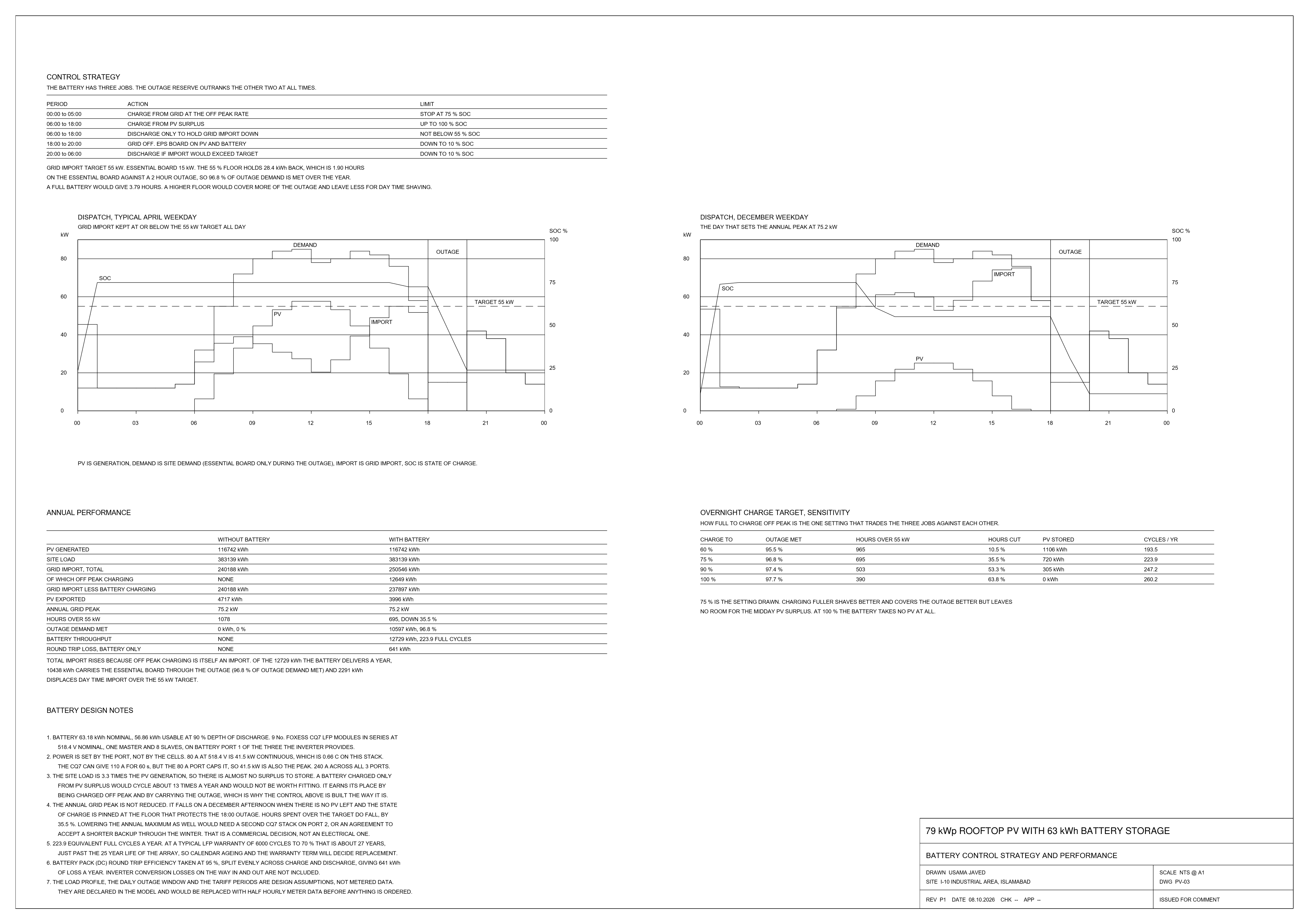
Dispatch was modelled hour by hour for a year in plain Python with no libraries, so every number can be traced by reading the file. Three jobs, in priority order: hold a reserve for the essential board through the evening outage, keep grid import under the maximum demand target, and soak up whatever PV would otherwise be exported.
| Period | Action | Limit |
|---|---|---|
| 00:00 to 05:00 | Charge from the grid at the off-peak rate | Stop at 75% SoC |
| 06:00 to 18:00 | Charge from PV surplus | Up to 100% |
| 06:00 to 18:00 | Discharge only to hold grid import down | Not below 55% |
| 18:00 to 20:00 | Grid off, EPS board runs on PV and battery | Down to 10% |
| 20:00 to 06:00 | Discharge if import would exceed the target | Down to 10% |
| Over a year | Without battery | With battery |
|---|---|---|
| PV generated | 116,742 kWh | 116,742 kWh |
| Site load | 383,139 kWh | 383,139 kWh |
| Grid import, total | 240,188 kWh | 250,546 kWh |
| of which off-peak charging | none | 12,649 kWh |
| Annual grid peak | 75.2 kW | 75.2 kW |
| Hours over the 55 kW target | 1,078 | 695, down 35.5% |
| Outage demand met | 0% | 96.8% |
| Battery throughput | none | 12,729 kWh, 223.9 full cycles |
| Round-trip loss, battery only | none | 641 kWh |
Total import rises because off-peak charging is itself an import. Of the 12,729 kWh the battery delivers in a year, 10,438 kWh carries the essential board through the evening outage and 2,291 kWh cuts daytime import above the target. The 55% floor holds 1.9 hours of reserve against a 2 hour outage, so 96.8% of outage demand is met. A higher floor would cover more of the outage and leave less for daytime shaving.
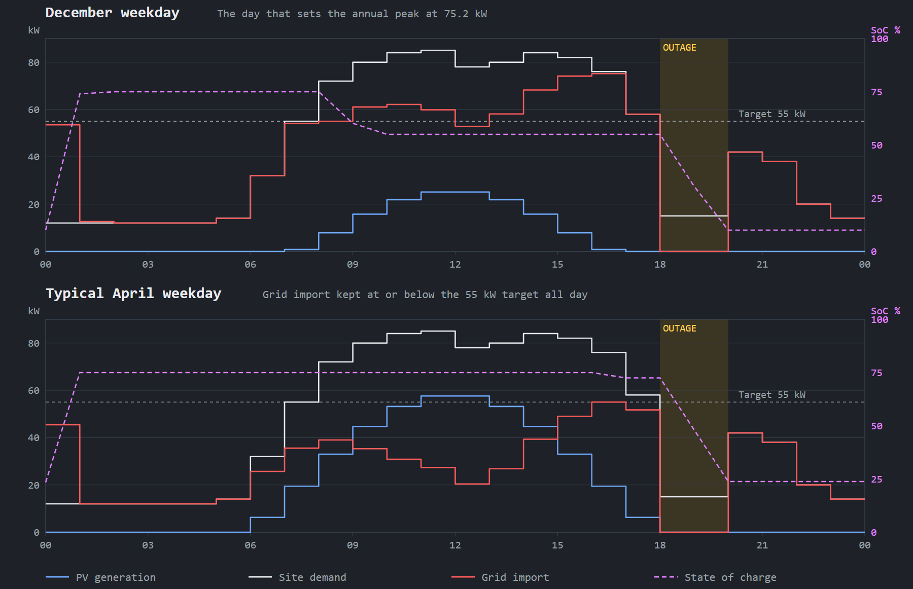
The annual peak does not move. It falls on a December afternoon when there is no PV left and the state of charge is pinned at the 55% floor that protects the 18:00 outage. Hours spent over the target do fall, by 35.5%. Lowering the maximum as well needs a second CQ7 stack on port two, or an agreement to accept a shorter backup through the winter. That is a commercial decision, not an electrical one.
How full to charge off-peak is the one setting that trades the three jobs against each other. Charging fuller shaves better and covers the outage better, but leaves no room for the midday PV surplus. At 100% the battery takes no PV at all.
| Off-peak charge target | Outage met | Hours over 55 kW | PV stored | Cycles a year |
|---|---|---|---|---|
| 60% | 95.5% | 965 | 1,106 kWh | 193.5 |
| 75%, the one drawn | 96.8% | 695 | 720 kWh | 223.9 |
| 90% | 97.4% | 503 | 305 kWh | 247.2 |
| 100% | 97.7% | 390 | none | 260.2 |
The cable schedule and the interface protection settings as they appear on PV-04. Lengths are design figures for this building. Cable sizes and volt drop are to be confirmed on the actual route, and the relay settings with IESCO, so the sheet stays at revision P3 until they are. Until then the relay values below are working figures, not approved settings.
| Tag | Cable | Length | Protection |
|---|---|---|---|
| W1 | 16 × 1C 6 mm² PV1-F | 45 m | None, one string per MPPT |
| W2 | 2 × 1C 35 mm² Cu XLPE | 8 m | QF1, 125 A DC, 2 pole |
| W3 | 4C 95 mm² Cu SWA | 32 m | QF2, 160 A MCCB |
| W4 | 4C 35 mm² Cu | 12 m | QF4, 63 A MCB |
| W5 | 1C 50 mm² green/yellow | 20 m | Main earthing conductor |
| Function | Setting | Trip time |
|---|---|---|
| 27 under voltage | 0.80 Un | 2.5 s |
| 27 stage 2 | 0.50 Un | 0.5 s |
| 59 over voltage | 1.15 Un | 1.0 s |
| 81 under frequency | 47.5 Hz | 0.5 s |
| 81 over frequency | 51.5 Hz | 0.5 s |
| ROCOF | 1.0 Hz/s | 0.5 s |
| Reconnect delay | After the grid returns | 180 s |
Equipment figures come from the FoxESS P3 Plus and CQ7 datasheets and the Jinko 72HL4-V datasheet. The load profile, the outage window and the tariff periods are design assumptions, declared at the top of the model, and would be replaced with half-hourly meter data before anything was ordered.
PV-01 mechanical (.pdf) PV-01 mechanical (.dwg) PV-03 battery control (.pdf) PV-03 battery control (.dwg) PV-04 single line diagram (.pdf) PV-04 single line diagram (.dwg)